Break points come first
Before any sheet is drawn, the line has to be broken into pieces. That decision is governed by three things: what the shop can fabricate and handle, what fits on the truck, and what a crew can physically lift and land in the space available.
What a spool sheet carries
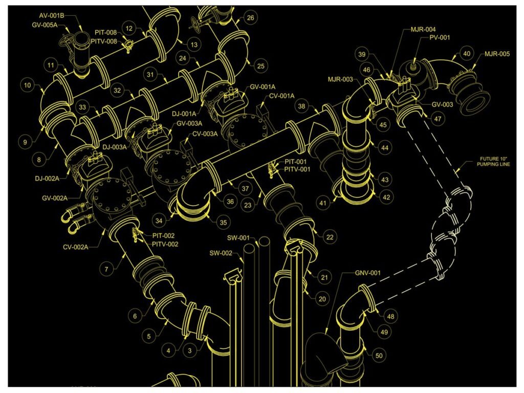
- A dimensioned isometric of the spool, with fittings and valves called out.
- Weld locations and weld numbering.
- A bill of material and a cut list.
- The piece mark, matching the tag that will be on the steel.
Piece marks and the field
Piece marks carry from the isometric to the spool sheet to the tag on the steel. When that chain holds, a delivery can be identified and installed without a phone call. When it breaks, the crew is unwrapping spools to figure out what they are looking at.
None of it works uncoordinated
Spools issued from an uncoordinated model fabricate cleanly and then fail to fit. It is the most expensive way to discover a clash, because by then you have paid for the material, the shop time and the delivery.
Sources
- Practice on process and mechanical piping packages for commercial and industrial projects.